
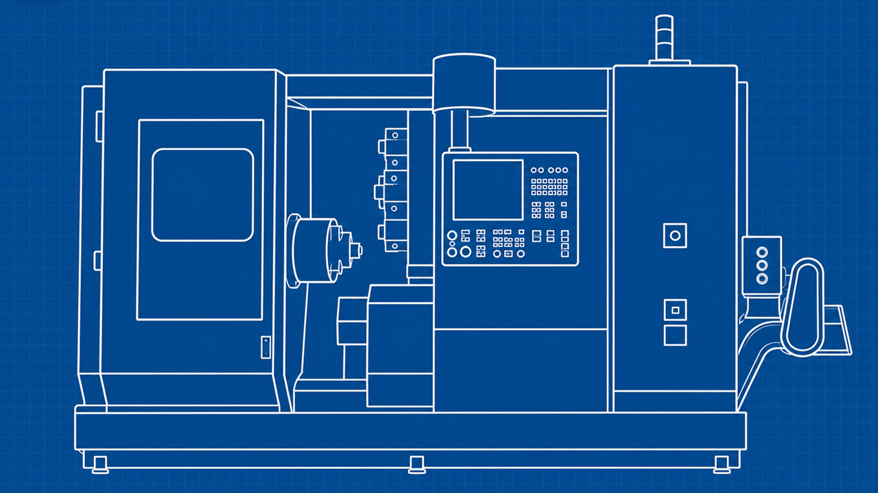
A CNC automatic lathe is a machine tool whose main sections — its units — work together to machine precision small parts from bar stock.
Understanding the role of each part makes it easier to interpret the specifications listed in catalogs, which in turn helps with machine selection.
Here we walk through the main elements that make up a CNC automatic lathe, one by one.
In This Article
- 1. The Main Spindle
- 2. The Guide Bushing (the Heart of the Swiss-Type)
- 3. The Tool Post
- 4. The Material-Feeding Device (Bar Feeder)
- 5. Chip Management and Coolant Supply
- The Parts Work Together in One Continuous Flow
- Know the Structure, and Catalogs Make Sense
- One System, Peripherals Included
- Frequently Asked Questions (FAQ)
- Summary
1. The Main Spindle
The main spindle grips and rotates the bar stock — it is the heart of a CNC automatic lathe.
The material spins at high speed while cutting tools engage it to machine the outside diameter, end faces, and so on. The spindle's rotational accuracy — how little it runs out — and its rigidity have a major impact on machining accuracy.
Many CNC automatic lathes also have a back spindle facing the main spindle.
A part whose outside diameter and threads have been machined on the main spindle is handed off to the back spindle, which faces and drills the opposite end — so both sides are machined in one continuous sequence and the part comes off finished.
2. The Guide Bushing (the Heart of the Swiss-Type)
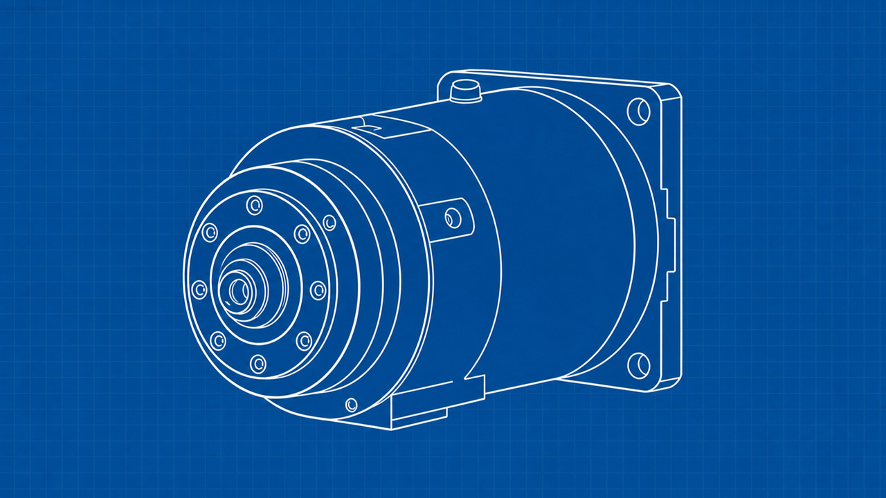
The guide bushing is the key component that defines Swiss-type (sliding-headstock) CNC automatic lathes.
It supports the bar stock right next to the point where the tool engages, suppressing runout and deflection of the material.
The material passes through the guide bushing and is machined as the headstock moves it back and forth. Because the workpiece is supported close to the cutting edge, even long, slender parts resist deflection, making high-precision machining easier.
This is why the Swiss-type is regarded as strong on slender, high-precision work.
For more detail, see The Role of the Guide Bushing.
Depending on the part, a non-guide-bushing configuration — one that does without the guide bushing — is sometimes chosen. Non-guide-bushing setups have advantages such as shorter remnant bar ends.
3. The Tool Post
The tool post is where the cutting tools (turning tools and the like) and rotary tools are mounted.
Multiple tools are mounted in advance and used in turn as machining progresses.
Tool posts come in two main types:
the gang type, which lines the tools up in a row like the teeth of a comb, and the turret type, which arranges the tools radially and rotates to index them.
The gang type switches tools quickly, making it well suited to high-speed volume production.
The turret type, on the other hand, can carry many tools, making it well suited to high-mix machining and complex shapes.
4. The Material-Feeding Device (Bar Feeder)
The bar feeder automatically feeds long bar stock into the machine.
Each time a part is machined from the bar, the feeder advances the material by the amount consumed, ready for the next part.
This automatic feeding lets machining continue without an operator standing by, supporting continuous production through unattended operation.
5. Chip Management and Coolant Supply
The equipment that evacuates chips generated during machining, and the coolant (cutting oil) supply that cools and lubricates the cutting edge, are also essential to stable operation.
In long stretches of unattended operation, reliable chip evacuation becomes especially important.
That is why technologies such as oscillation cutting and high-pressure coolant systems are put to use.
The Parts Work Together in One Continuous Flow
With these elements working together, a CNC automatic lathe runs from bar-stock feeding through machining to part ejection as a single flow.
Concretely: feed the bar stock → rotate it with the main spindle → support it with the guide bushing → cut it with the tools on the tool post → machine the reverse side with the back spindle → eject the finished part.
Being able to repeat this whole sequence continuously is the defining strength of the CNC automatic lathe.
With each part's role clear, the differences between models also become easier to understand.
Know the Structure, and Catalogs Make Sense
The big benefit of understanding each part's role is that catalog specifications become much easier to decode.
A CNC automatic lathe catalog lists items such as "maximum machining diameter," "headstock stroke," "number of tools," "maximum drilling capacity," and "maximum tapping capacity."
Each of these ties directly to the structures we have just covered.
For example, "maximum machining diameter" indicates the bar diameter the machine can handle, "number of tools" is how many tools the tool post can carry, and "headstock stroke" indicates, on a Swiss-type, the length that can be machined in one material feed.
If you understand the structure, these figures become material for judging whether the machine can handle your parts.
Look only at the specs without knowing the structure, and the numbers are hard to interpret.
Understanding the basic structure is knowledge you need for sound machine selection.
One System, Peripherals Included
A CNC automatic lathe is not a machine that stands complete on its own.
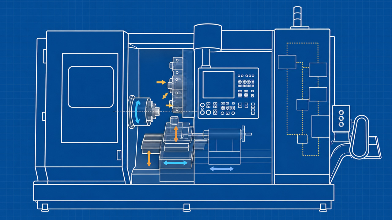
It is used in combination with a range of peripheral equipment: a bar feeder that supplies bar stock, a chip conveyor that carries chips out, a coolant system that circulates cutting oil, and a device that collects finished parts.
Working together, these turn the CNC automatic lathe into a production system capable of unattended operation.
When adopting a machine, it is important to evaluate the whole picture — peripherals included — not just the performance of the machine itself.
Especially for unattended operation, whether chip management and part collection run reliably has a major effect on the machine's utilization rate.
Frequently Asked Questions (FAQ)
Q. Do all machines have a guide bushing?
A. No. The guide bushing is the defining component of Swiss-type (sliding-headstock) CNC automatic lathes.
Fixed-headstock machines do not use one. Some Swiss-type models can also be switched between guide-bushing and non-guide-bushing configurations.
Q. What is the benefit of having a back spindle?
A. The back spindle takes over a part machined on the main spindle and continues machining the opposite side. Because both sides can be finished on one machine, it enables process integration and fewer downstream operations, and machining accuracy is easier to maintain.
Q. What does "maximum machining diameter" in a catalog mean?
A. It is the approximate maximum diameter of bar stock the machine can handle.
Whether the bar diameters you use fall within this range is a basic checkpoint in machine selection.
Summary
A CNC automatic lathe is a machine in which the main spindle, guide bushing, tool post, and material-feeding device work together to machine precision parts continuously from bar stock.
Understanding the structure of each part gives you a solid foundation for decoding catalog specifications and making the right machine selection.
Next, take a look at oscillation cutting, a machining technique distinctive to automatic lathes.